


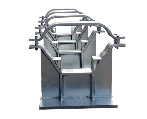
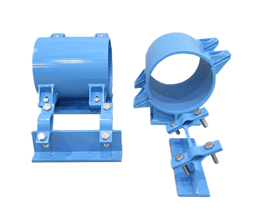
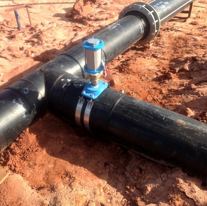
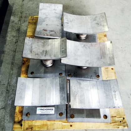
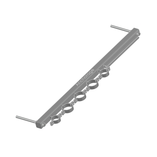
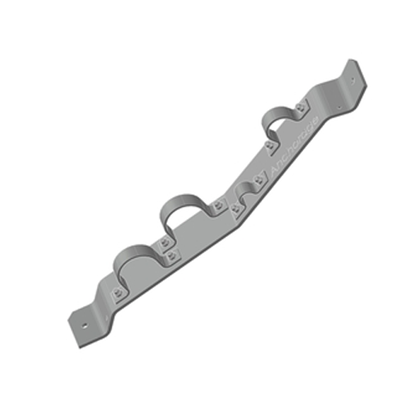
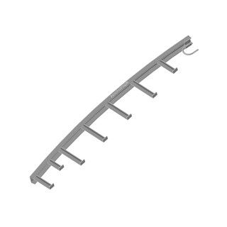

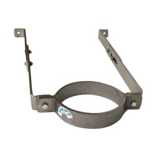
Custom pipe shoes are available for all pipe diameters, featuring options for insulation, PTFE sliders, and various lining material for the clamps. We have produced sizes ranging from as small as 10mm right up to 2m and are always open to new challenges.
- Products
-
-
-
Categories
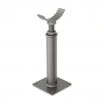
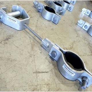
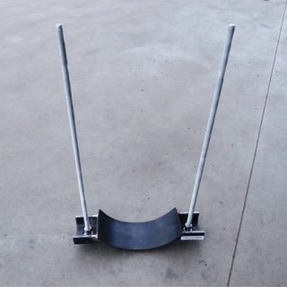
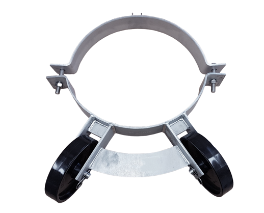
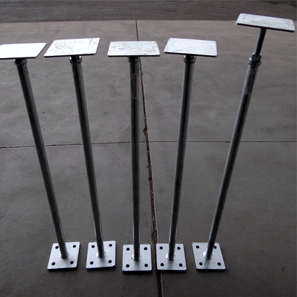
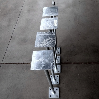
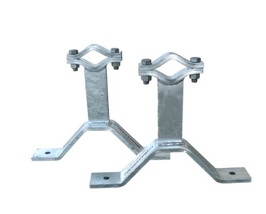
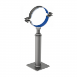
 AG630
AG630HEIGHT ADJUSTABLE SUPPORT - CRADLE MOUNT
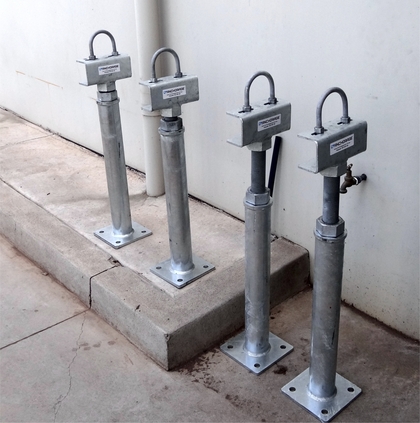
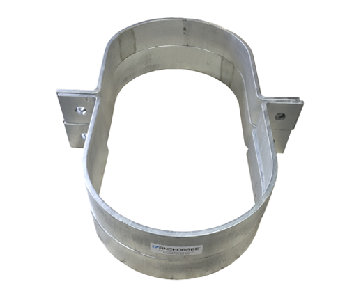
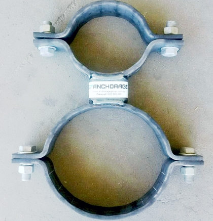
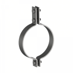
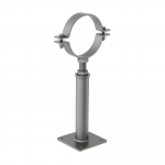 AG631
AG631HEIGHT ADJUSTABLE SUPPORT - CLAMP MOUNT
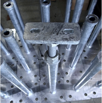
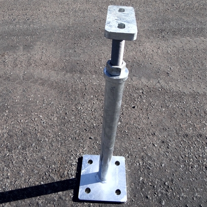
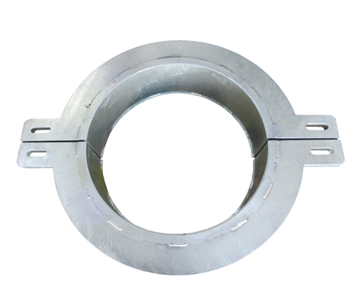
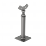 AG632
AG632HEIGHT ADJUSTABLE FLANGE MOUNT
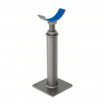 AG634
AG634INSULATED HEIGHT ADJUSTABLE SUPPORT - CRADLE MOUNT
 AG636
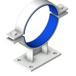
AG636INSULATED HEIGHT ADJUSTABLE SUPPORT - CLAMP MOUNT
 AG100
AG100LIGHT DUTY 2-BOLT PIPE CLAMP
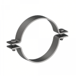
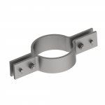
 AG110
AG110MEDIUM DUTY 2-BOLT PIPE CLAMP
 AG112
AG1122-BOLT CLAMP FOR DICL PIPE
 AG115
AG1152-BOLT CLAMP FOR HDPE PIPE
 AG120
AG120HEAVY DUTY 2-BOLT PIPE CLAMP
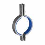
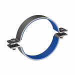 AG130
AG130INSULATED 2-BOLT PIPE CLAMP
 AG150
AG150LIGHT DUTY 3-BOLT PIPE CLAMP
 AG160
AG160MEDIUM DUTY 3-BOLT PIPE CLAMP
 AG170
AG170HEAVY DUTY 3-BOLT PIPE CLAMP
 AG190
AG1903-BOLT PIPE CLAMP FOR HIGH TEMPERATURES
 AG200
AG200INSULATED 3-BOLT PIPE CLAMP
 AG220
AG220LOW TEMPERATURE RISER SUPPORT
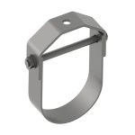 AG250
AG250CLEVIS CLAMP
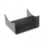
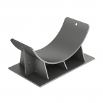 AG550
AG550HEAVY DUTY PIPE CRADLE
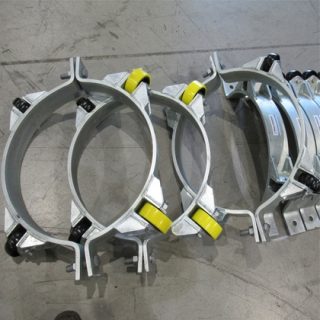
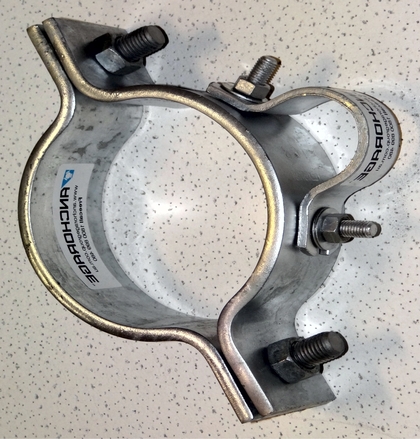
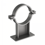
 AG560
AG560CLAMPED PIPE SHOE
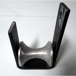
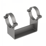
 AG565
AG565SINGLE PIPE SHOE
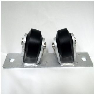
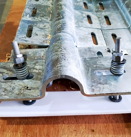
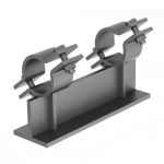
 AG570
AG570DOUBLE PIPE SHOE
 AG580
AG580WELD-ON PIPE SHOE
 AG585
AG585INSULATED SINGLE PIPE SHOE
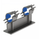
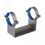 AG590
AG590INSULATED DOUBLE PIPE SHOE
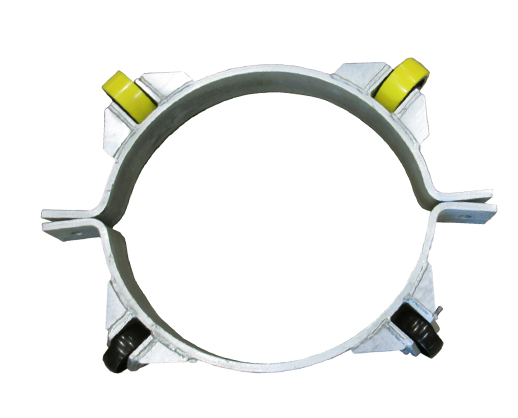
 AG595
AG595INSULATED CLAMPED PIPE SHOE AG595
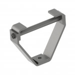
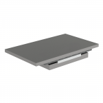 AG620
AG620SLIDE PLATE
 AG412
AG412SADDLE CLAMP FOR DICL PIPE
 AG415
AG415SADDLE CLAMP FOR HDPE PIPE
 AG420
AG420SADDLE GUIDE
 AG430
AG430SADDLE CLAMP
 AG440
AG440INSULATED SADDLE CLAMP
 AG445
AG445INSULATED SADDLE GUIDE
 AG470
AG470U-BOLT PIPE GUIDE
 AG475
AG475U-BOLT GUIDE FOR HDPE PIPE
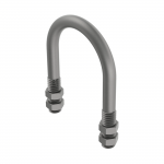 AG480
AG480U-BOLT PIPE CLAMP
 AG485
AG485U-BOLT CLAMP FOR HDPE PIPE
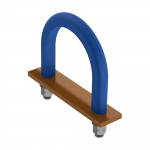 AG490
AG490INSULATED U-BOLT PIPE CLAMP
 AG495
AG495INSULATED U-BOLT CLAMP FOR HDPE PIPE
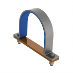
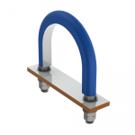
 AG510
AG510INSULATED U-BOLT GUIDE
 AG515
AG515INSULATED U-BOLT GUIDE FOR HDPE PIPE
 AG530
AG530TEFLON INSULATED U-BOLT GUIDE
 AG260
AG260BEAM CLAMP
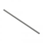 AG270
AG270FULLY THREADED ROD
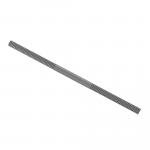 AG280
AG280DROP ROD RH/LH
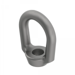 AG290
AG290FORGED WELDLESS EYE NUT
 AG295
AG295SPADE NUT
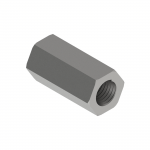 AG310
AG310HEX CONNECTOR / COUPLER NUT
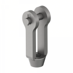 AG320
AG320FORGED CLEVIS & PIN
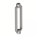 AG330
AG330FORGED TURNBUCKLE
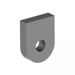
 AG340
AG340PIPE LUG
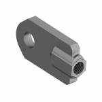
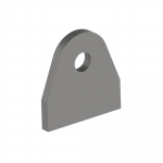
 AG350
AG350WELDED LUG
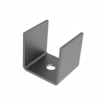 AG360
AG360WELDED BEAM ATTACHMENT
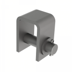 AG370
AG370WELDED BEAM ATTACHMENT WITH LOAD PIN
 AG385
AG385HEMISPHERICAL CUP & WASHER
-
-
-