Friction as Primary Axial Restraint in Pipe Supports
Why relying on clamp friction alone is not a defensible design basis, and what to specify instead
Prepared by Roger Shemilt, Technical Director, Swift Metal Australia
Executive Summary
As pipe support specialists, we regularly encounter design scenarios that could compromise the integrity of the broader pipework project if we simply supplied the parts. We’ve prepared this whitepaper on using friction as the primary axial restraint to share the knowledge we’ve gained on this topic.
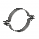
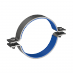
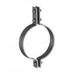
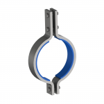
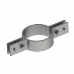
Pipe clamps are sometimes proposed as the primary axial restraint for a pipe support, using the friction between the clamp and the pipe to resist movement along the pipe’s length. This is generally not advisable as a design basis.
Friction is a variable, condition-dependent effect. It is not a fixed, verifiable quantity like a mechanical stop or an anchor. Standard industry practice treats friction arising from thermal movement as a load to be calculated and accommodated, not as a restraint capacity to be relied on.
Where a support genuinely needs to prevent axial movement, whether to protect connected equipment, maintain pipe alignment, or preserve system integrity, the preferred approach is a positive mechanical restraint: a stop, anchor or guide with a defined, inspectable load path. This paper sets out the technical reasoning, the standards that support it, and the design alternatives that should be specified instead.
The Problem with Friction as a Restraint
An axial restraint is meant to be a dependable boundary condition. It needs to hold a known, verifiable amount of load, in a known direction, for the life of the asset. Friction, by definition, is an unreliable method.
The effective coefficient of friction between a clamp and a pipe, and the clamp’s normal force against the pipe, both change over time and with conditions. Contributing factors include:
Coating condition and wear at the clamp-to-pipe interface
Corrosion products building up between the surfaces
Moisture or oil contamination changing the effective friction coefficient
Embedment or creep of the coating or gasket material under sustained load
Bolt relaxation over time, reducing clamp normal force
Vibration, which can progressively loosen a friction joint
Thermal cycling, which affects both coating behaviour and pipe diameter, and therefore bolt tension.
Because these factors interact and change over the asset’s operating life, it becomes very difficult to demonstrate a reliable, auditable minimum axial capacity for a friction-based restraint at any given point in time, let alone across a twenty or thirty year design life.
Relevant Industry Standards
This is not a novel position. It is consistent with how friction is treated across the standards and design guidance most commonly referenced in piping and pipe support design.
Standard
What it covers
Relevance to friction as restraint
PIP STC01015 – Structural Design Criteria
Directs designers to calculate pipe-rack friction loads from thermal sliding using static coefficients, treated as a temporary thermal load.
Friction is a load to be resisted, not a restraint to design around.
ASME B31.3 – Process Piping
Addresses forces generated when thermal movement is impeded by connected equipment and restraints such as guides and anchors.
Where restraint is genuinely required, the code frames it as an intentional, defined element, not an assumed friction condition.
DIPRA – Thrust Restraint Design for Ductile Iron Pipe
Notes that frictional resistance is unpredictable and should not be relied on as longitudinal restraint, in the context of joint restraint design.
Same underlying principle applies to clamp friction: uncertain friction should not be credited as restraint capacity.
ANSI/MSS SP-58 – Pipe Hangers and Supports
Sets out accepted industry practice for selecting, applying and installing pipe hangers and supports, including movement control.
Reinforces that movement is controlled through defined support and restraint types, not uncontrolled friction behaviour.
The pattern across all four references is the same: friction is either explicitly identified as a load effect to be calculated and absorbed elsewhere in the design, or it is flagged as too unpredictable to be credited as a restraint capacity. None of them treat friction as an acceptable primary restraint mechanism.
Why Friction-Only Restraint Fails in Practice
Stick-slip behaviour
A friction-based restraint does not fail gradually or predictably. It tends to alternate between holding (stick) and releasing (slip) across operating cycles as the pipe heats, cools, and moves. Each slip event can shift where load is picked up by adjacent supports, which changes the load path the system was originally designed around. This makes both the initial analysis and any later field verification considerably more complex than for a positive stop or anchor, where the load path is fixed and known.
Consequences of a slip event
If friction capacity is lost at an unplanned moment, the pipe is free to move, placing unwarranted pressure on other elements of the pipe system: valves, elbows, instrumentation or other connected equipment.
That is not simply a case of a bit more movement than expected. It can introduce an entirely different load case: impact loading, overstress points of moment, overload on connected equipment or nozzles, or overload on adjacent supports that were never designed to pick up that force.
Preferred Design Alternatives
Where axial restraint is required, the following options give a defined, verifiable load path and are the preferred specification in place of friction alone.
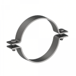
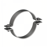
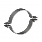
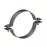
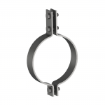
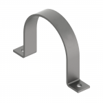
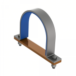
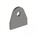
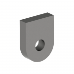
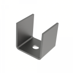
Clamp plus positive stop (recommended default). Retain the clamp as the pipe attachment, but transfer axial load through a mechanical stop, key or lug bearing directly against structure, with a defined gap and clear directionality.
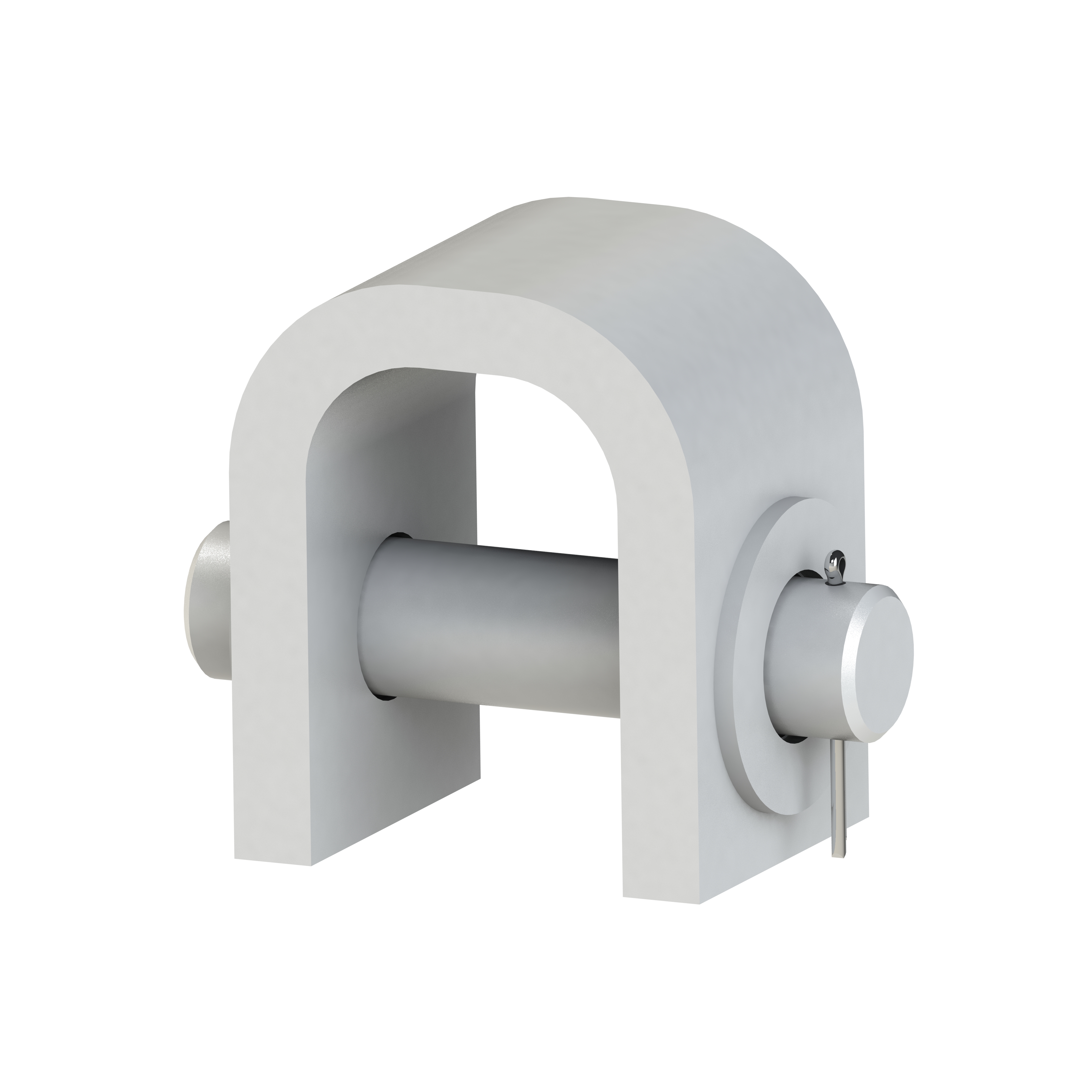
Guides plus line stops. Use guides to manage lateral movement and dedicated line stops or limit stops to control axial travel in one or both directions, with gaps specified to accommodate thermal expansion without picking up unintended load.
Anchor at critical points. Where analysis shows axial restraint is essential, for example to protect equipment nozzles or expansion joints, provide a proper anchor with a clear, calculable load path into primary structure or foundation.
If Friction-Based Restraint Is Still Required
There are cases where a client or project insists on a friction-based concept. If that happens, it should be treated as a degraded-capacity, non-linear restraint, not a standard design solution, and should not proceed without a documented verification and maintenance basis covering, at minimum:
A defensible lower-bound friction coefficient for the actual interface materials and the full range of lifecycle conditions (coatings, corrosion, contamination)
A defensible lower-bound clamp normal force, accounting for bolt relaxation, embedment, temperature effects and installation tolerances, with a stated method for controlling and inspecting it
Evidence that a single slip event will not cause overstress, nozzle overload, or impact at adjacent restraints, supported by credible displacement bounds
An inspection and maintenance plan to preserve clamp preload and interface condition over the asset’s life
A secondary mechanical travel limit, so that loss of friction cannot lead to uncontrolled pipe migration
In practice, once all of this is documented and controlled, the friction-based option usually costs more in engineering and ongoing maintenance than simply specifying a mechanical stop or anchor from the outset.
Conclusion
Friction has a place in pipe support design as a load effect to be calculated and accommodated. It does not have a place as the primary means of axial restraint. The standards most commonly cited in this area consistently support that position, and the practical failure modes, stick-slip behaviour and uncontrolled migration after a slip event, are difficult and costly to design around after the fact.
Where a project needs genuine axial restraint, consult with your pipe stress engineer to identify the best product to specify: a stop, a guide, or an anchor with a defined and inspectable load path. It is a simpler design, a simpler review, and a more reliable outcome over the life of the asset.
Get a quick quote and download design files free, straight from any product page.
[1] Process Industry Practices (PIP), STC01015, Structural Design Criteria, sections addressing thermal loads and friction loads (e.g. 4.1.7.5 – 4.1.7.8). [2] ASME B31.3, Process Piping, section 319.2.1, restraints and thermal movement (as commonly paraphrased in industry guidance). [3] Ductile Iron Pipe Research Association (DIPRA), Thrust Restraint Design for Ductile Iron Pipe, Seventh Edition, last revised May 2016, discussion of the unpredictability of frictional longitudinal restraint. [4] ANSI/MSS SP-58-2018, Pipe Hangers and Supports – Materials, Design, Manufacture, Selection, Application, and Installation, Manufacturers Standardization Society (MSS).

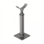
 AG630